My Role
UX Design Manager,
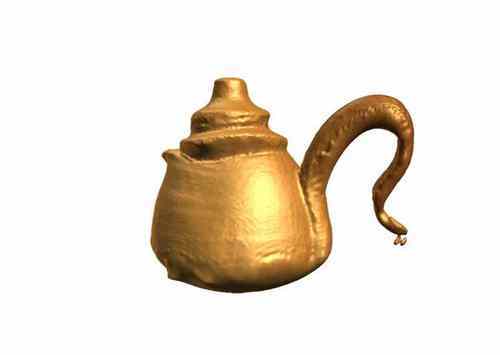
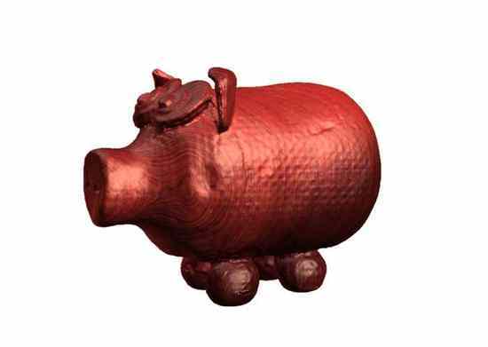
3D Capture
- Led UX design for the 3D Capture feature end-to-end
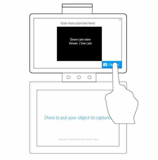
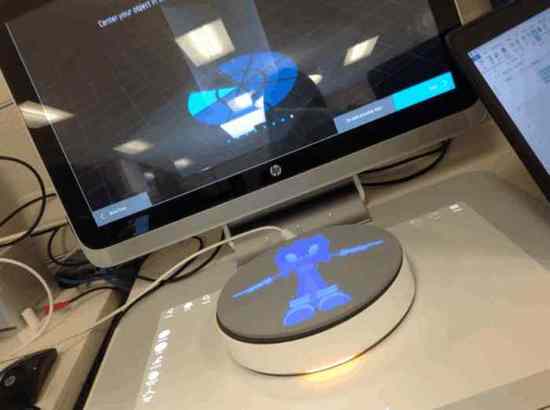
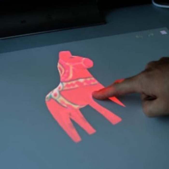
- Mapped the full physical-digital interaction loop
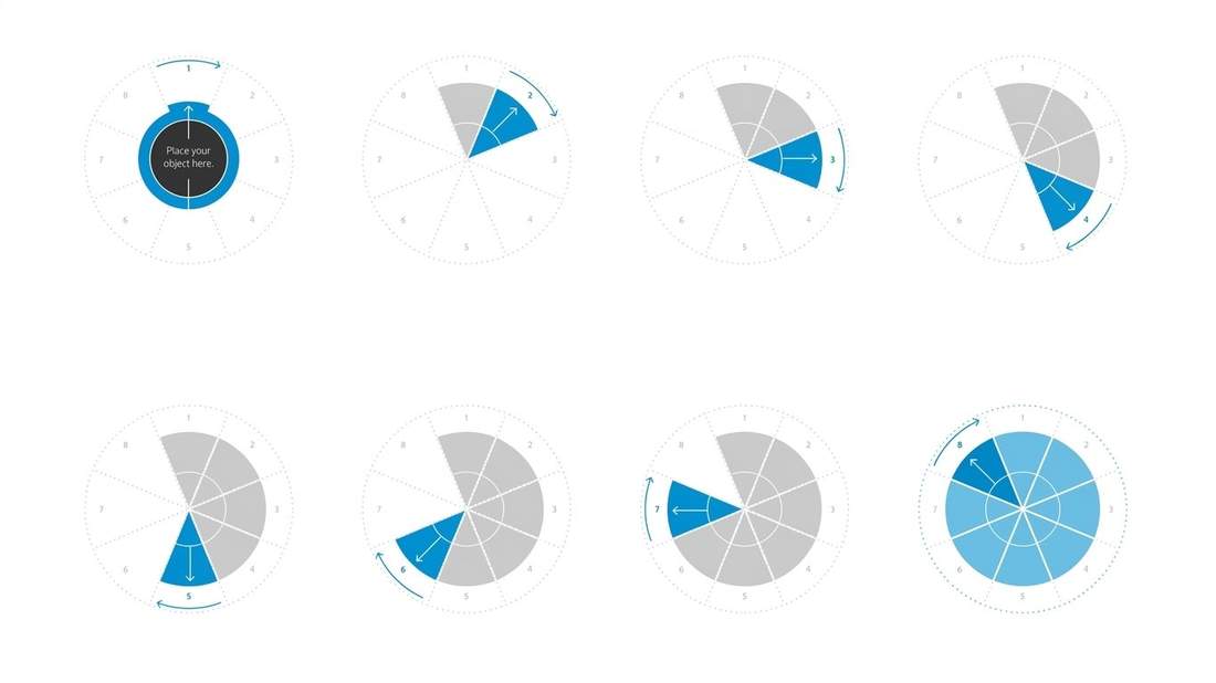
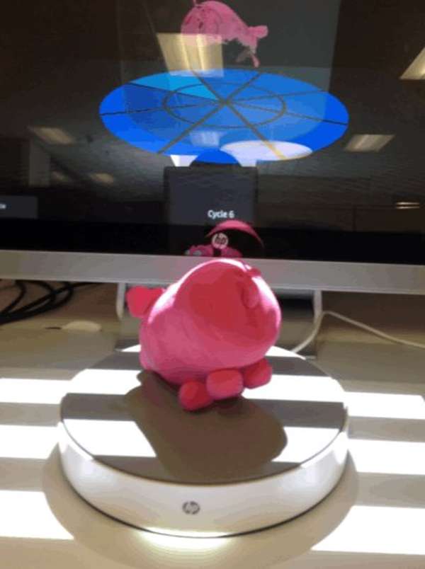
- Designed the 8-cycle scan model and pie-chart progress system
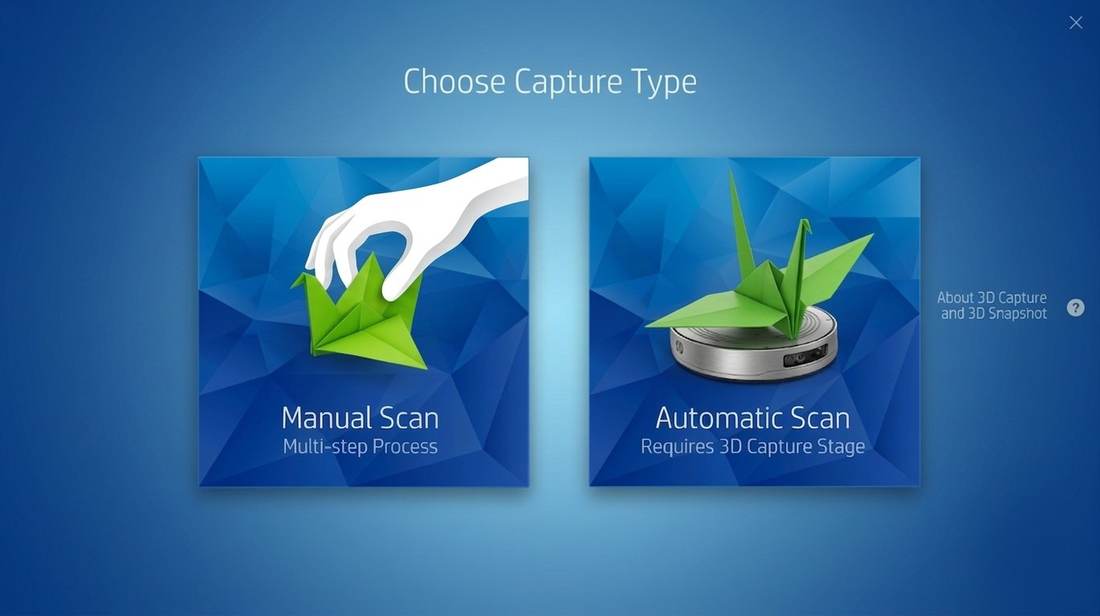
- Defined Manual vs. Automatic mode interaction grammar
- Prototyped alongside mechanical engineering and CV teams
- Ran user research sessions with a wide range of test objects
- Facilitated cross-functional alignment across hardware and software
- Contributed to HP spatial computing design guidelines
Reflection
What I'd Do
Differently
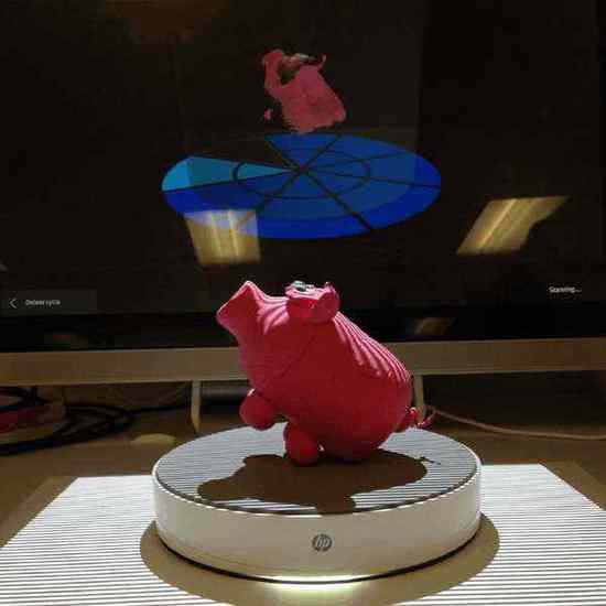
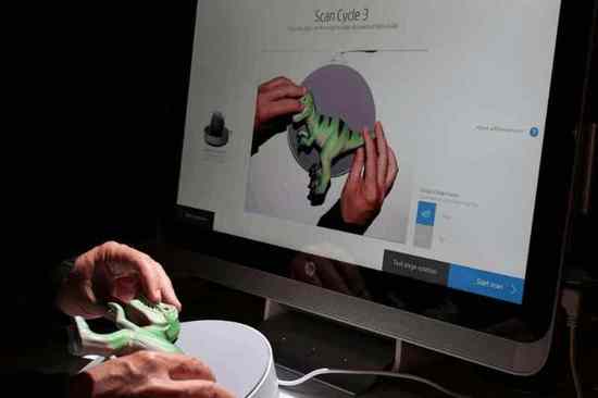
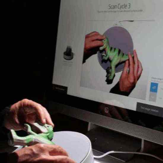
I would advocate for earlier longitudinal testing with the physical hardware. Wizard of Oz methods were invaluable early on, but the transition to actual hardware revealed failure modes — especially the projected guide's visibility under ambient light — that we hadn't fully anticipated.
I'd also push harder for a dedicated first-run onboarding experience. The system was genuinely novel and we relied too heavily on in-context guidance. A brief first-time setup flow would have reduced the learning curve without adding friction for returning users.
Looking forward, voice coaching and AI make this process dramatically simpler. Instead of an 8-step manual repositioning cycle, an AI-powered system could analyse the mesh in real time and instruct users — or the stage itself — to only capture the angles that are actually missing. Move the object only when the computer can't see it.